 |
DirectOuput Framework R2
DirectOutput framework R2 for virtual pinball cabinets
|
Go to: Overview |
 |
DirectOuput Framework R2
DirectOutput framework R2 for virtual pinball cabinets
|
Go to: Overview |
Artnet is a industry standard protocol used to control DMX lighting effects over ethernet. Using Art-Net it is possible to connect a very wide range of lighting effects like strobes or dimmer packs. There are tons of DMX controlled effects available on the market (from very cheap and small to very expensive and big). It might sounds a bit crazy, but with Art-net and DMX you could at least in theory control a whole stage lighting system (this would likely make you feel like Tommy in the movie).
To use Art-Net you will need a Art-Net node (unit that converts from ethernet to DMX protocol) and also some DMX controlled lighting effect. There are quite a few different Art-Net nodes available on the market and most of them should be compatible with the DirectOutput framework. For testing the Art-Net node sold by Ulrich Radig as a DIY kit was used.
Each Art-Net node/DMX universe supports 512 DMX channels and several Art-Net nodes controlling different DMX universes can be used in parallel.
If you want to read more about Art-net, visit the website of Artistic License. The specs for Art-net can be found in the Resources - User Guides + Datasheets section of the site.

A configuration section for ArtNet might resemble the following structure:
ArtNet has the following 3 configurable properties:
String containing broadcast address. If this parameter is not set the default broadcast address (255.255.255.255) will be used. Valid values are any IP adresses (e.g. 192.168.1.53).
The name of the item.
The number of the Dmx universe.
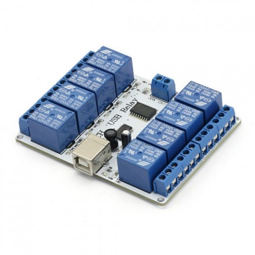
This is a generic output controller class which are based on the FT245R chip (http://www.ftdichip.com/Products/ICs/FT245R.htm). Only units using the chip in bitbang mode are supported by this output controller class. The SainSmart USB relay boards (http://www.sainsmart.com/arduino-compatibles-1/relay/usb-relay.html) are compatible with this output controller, but other hardware which is based on the same controller chip might be compatible as well. Generally controller units which is exclusively using the FT245R (no extra cpu on board) and having max. 8 output ports are likely to be compatible. Please let me know, if you have tested other hardware successfully, so I can ammend the docu.

Thanks go to DJRobX for his early implementation of a SainSmart output controller which was the starting point for the implementation of this class.
A configuration section for FT245RBitbangController might resemble the following structure:
FT245RBitbangController has the following 2 configurable properties:
The name of the item.
The serial number of the FT245R chip which is to be controlled.
The LedWiz is a easy to use outputcontroller with 32 outputs which all support 49 pwm levels with a PWM frequency of approx. 50hz. The LedWiz is able to drive leds and smaller loads directly, but will require some kind of booster for power hungery gadgets like big contactors or motors.

The DirectOutput framework does fully support the LedWiz and can control up to 16 LedWiz units.
The framework can automatically detect connected LedWiz units and configure them for use with the framework.
The LedWiz is made by GroovyGameGear and can by ordered directly on GroovyGamegears website, but also from some other vendors.
This unit was the first output controller which was widely used in the virtual pinball community and was the unit for which the legacy vbscript solution was developed. The DirectOutput framework replaces the vbscript solution, but can reuse the ini files which were used for the configuration of the tables. Please read ledcontrolfiles for more information.
The current implementation of the LedWiz driver uses a separate thread for every ledwiz connected to the system to ensure max. performance.

A configuration section for LedWiz might resemble the following structure:
LedWiz has the following 2 configurable properties:
The name of the item.
The unique number of the LedWiz (Range 1-16).
This is a dummy output controller not doing anthing with the data it receives.
It is mainly thought as a sample how to implement a simple output controller.
Be sure to check the abstract OutputControllerBase class and the IOutputController interface for a better understanding.
A configuration section for NullOutputController might resemble the following structure:
NullOutputController has the following 1 configurable properties:
The name of the item.
The PacDrive is a simple output controller with 16 digital/on off outputs.
DOF supports a the use of 1 PacDrive unit. This unit can be detected and configured automatically. If auto configuration is used, the generated LedWizEquivalent toy for the PacDrive will have number 19. This means that ini files numbered with 19 are automatically used to configure a PicDrive unit.
The outputs are by default turned on when the PacDrive unit is powered up. This controller class will turn off the PacDrive outputs upon initialisation and when it is finished.
This unit is made and sold by Ultimarc.

A configuration section for PacDrive might resemble the following structure:
PacDrive has the following 1 configurable properties:
The name of the item.
The PacLed64 is a output controller with 64 outputs all supporting 256 pwm levels with a PWM frequency of 100khz. Since the outputs of the unit are constant current drivers providing 20ma each, leds can be connected directly to the outputs (no resistor needed), but booster circuits must be used to driver higher loads (e.g. Cree leds). Up to 4 PacLed64 controllers can be used with the DirectOutput framework.
The framework supports auto detection and configuration of these units. If auto config is used, two LedWizEquivalent toys are added for each connected PacLed64. The numbers of the LedWizEquivalents are based on the Id of the PacLed64. Id1=LedwizEquivalent 20+21, Id2=LedwizEquivalent 22+23, Id3=LedwizEquivalent 24+25, Id4=LedwizEquivalent 26+27. If the numbers of ini files used for the configuration match these numbers, they will be used to set up the effects for the table.
This unit is made and sold by Ultimarc.
The implemention of the PacLed64 driver uses a separate thread per connected unit to ensure max. performance.

A configuration section for PacLed64 might resemble the following structure:
PacLed64 has the following 2 configurable properties:
The unique Id of the PacLed64 (Range 1-4).
The name of the item.
This output controller class is used to control the WS2811 led strip controller by Swisslizard.
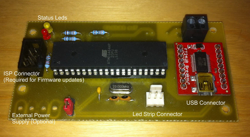
The hardware of this controller is based on a Atmel microcontroller and a FT245R USB interface chip by FTDI. To ensure max performance all copde on the controller has been written in assembler.
WS2811 is a small controller chip which can controll a RGB led (256 PWM level on each channel) and be daisychained, so long cahins of LEDs (led strip are possible. The WS2812 understands the same protocoll as the WS2811, but is a RGB led with integrated controller chip which allows for even more dense populated RGB strips.
Those controller chips are controlled using a single data line (there is no clock line). The data has to be sent with a frequency of 800khz. 1 bits have a duration of 0.65uS high and 0.6uS low. 0 bits have a duration of 0.25uS high and 1uS low. A interuption in the dataflow triggers the controller chips to push the data in the shift register to the PWM outputs. Since the timing requirements are very strict it is not easily possible to output that signal directly from a computer with normal operating system. Thats why controllers like the one displayed below are needed.

This is a image of my controller prototype with classical through the hole parts and a small breakoutboard by SparkFun. At the time of the release of DOF R2, the first prototypes of SMD version of the controller are in production. Check back in the forums for more information.
A configuration section for WS2811StripController might resemble the following structure:
WS2811StripController has the following 3 configurable properties:
The number of the WS2811 strip controller.
The name of the item.
The number of leds on the WS2811 based led strip.